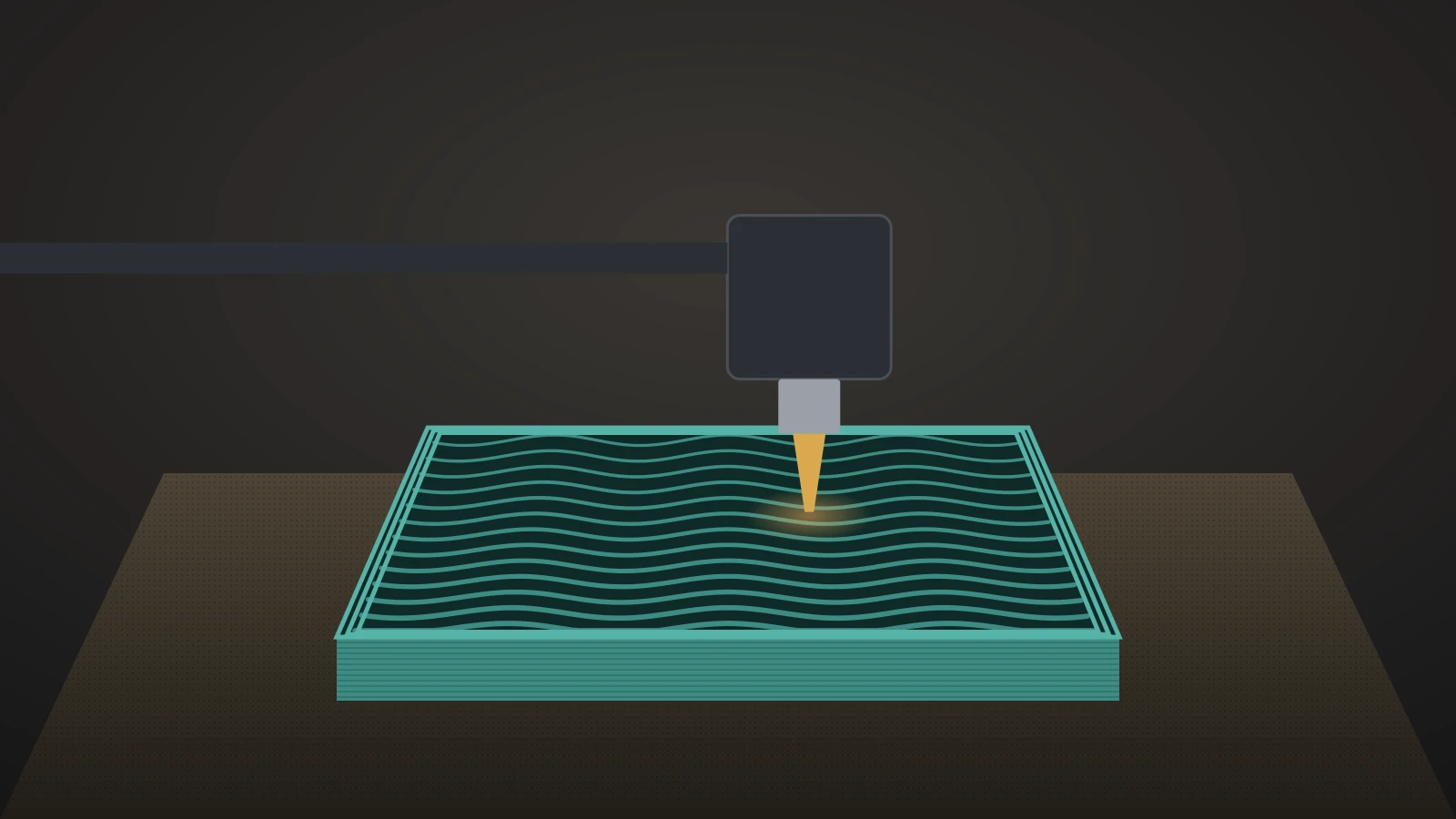
3D printing tolerances describe how far a printed part may differ from its CAD size. For parts that fit together on a well-tuned FDM printer, design a gap of about 0.15–0.40 mm depending on the fit. Prusa says its printers are accurate to at least 0.2 mm, resin printers hold tighter, and a test print confirms the value.
Joints, snap fits and hinges have their own guide on 3D printed joints. This article covers the numbers behind any fit: how accurate printers are, how much clearance to add, why holes shrink, which slicer settings correct it and how to make screws and threads work.
The short answer
- Typical accuracy: about 0.2 mm on a Prusa printer (Prusa’s own figure); Formlabs lists FDM at ±0.5% with a ±0.5 mm lower limit and resin at ±0.15% on small features.
- Clearance to add: 0.15–0.20 mm for snug alignment, 0.20–0.25 mm for sliding parts, 0.30–0.40 mm for loose or print-in-place parts (University of Florida makerspace, Prusa MK4 and XL).
- Holes print small because circles become polygons and plastic rounds the corners; fix flow, then use X-Y hole compensation.
- Test before you trust: OrcaSlicer’s tolerance test checks gaps from 0.0 to 0.4 mm in one small print.
- Threads: print them only at M6 and larger; use heat-set inserts or nuts for small screws (Formlabs).
What are 3D printing tolerances?
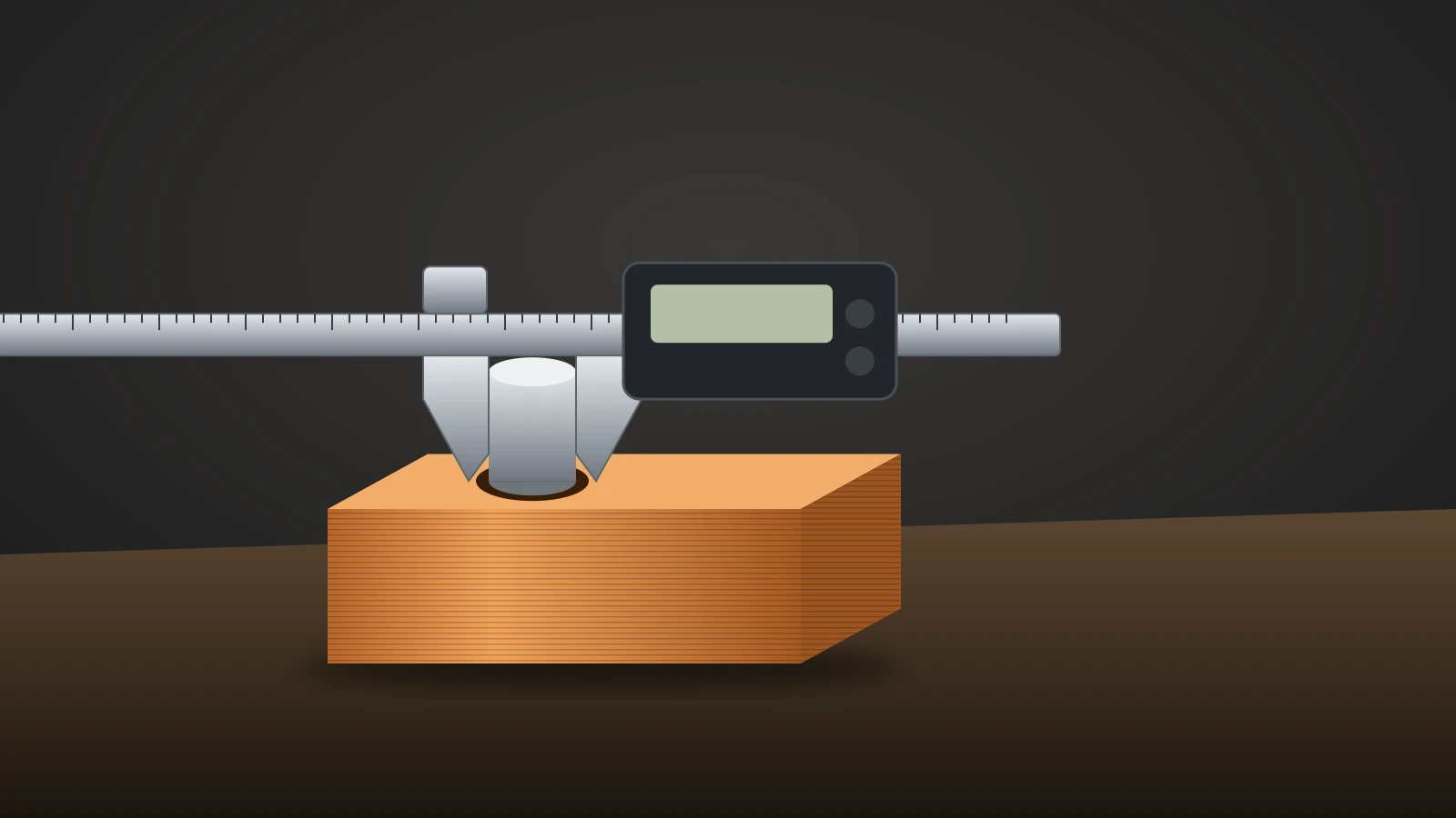
A 3D printing tolerance is the amount a printed dimension is allowed to differ from the design. The University of Florida’s Marston Makerspace separates two terms that are often mixed up: a tolerance is the allowed variation of one feature, and a clearance is the gap you deliberately design between two mating parts.
Filament shows the idea on a small scale. Prusament PLA is rated at 1.75 mm ±0.02 mm, so any spool between 1.73 and 1.77 mm is in spec. Printers have tolerances too: extrusion behavior, cooling shrinkage and layer-by-layer building make parts come out slightly larger or smaller than the model.
Prusa lists what moves the result: the size of the model, horizontal or vertical orientation, the shape of the interlocking parts, calibration, slicer settings and the material.
3D printer tolerance by technology: FDM, resin and powder
Resin and powder printers hold tighter tolerances than filament (FDM) printers, though a calibrated FDM machine is accurate enough for most fitting parts. Formlabs, which makes resin and powder printers, gives these typical figures:
| Technology | Typical tolerance (Formlabs) |
|---|---|
| Resin: stereolithography (SLA) and digital light processing (DLP) | ±0.15% for features 1–30 mm, ±0.2% for 31–80 mm, ±0.3% for 81–150 mm; lower limit ±0.02 mm |
| Powder: selective laser sintering (SLS) and multi jet fusion (MJF) | ±0.5% or 0.3 mm, whichever is larger |
| Filament: fused deposition modeling (FDM) | ±0.5%, lower limit ±0.5 mm |
Prusa, a filament printer maker, says its own printers are accurate to at least 0.2 mm, tighter than Formlabs’ general FDM figure. Material matters too: Formlabs notes ABS warps more than PLA because it shrinks more as it cools.
If accuracy decides your choice of printer, our comparison of resin vs filament printing covers the other trade-offs.
How much tolerance to add for 3D printing
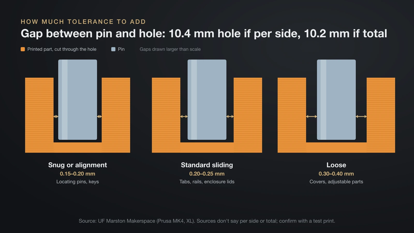
Design a gap of about 0.2 mm between the mating surfaces of parts that should slide together on a tuned FDM printer, less for a snug fit and more for loose or moving parts. These starting values come from the University of Florida’s makerspace on Prusa MK4 and XL printers, with Prusa’s and Formlabs’ guidance alongside:
| Fit | Clearance to design in | Typical use | Source |
|---|---|---|---|
| Press or interference fit | Below 0.15 mm; find it by testing | Pegs and pins meant to stay put | Below the UF snug range; confirm with OrcaSlicer’s 0.0–0.1 mm test holes |
| Snug or alignment | 0.15–0.20 mm | Locating pins, keys | UF Marston Makerspace |
| Standard sliding | 0.20–0.25 mm | Tabs, rails, enclosure lids | UF Marston Makerspace |
| Loose | 0.30–0.40 mm | Covers, adjustable parts | UF Marston Makerspace |
| Moving parts, first try | At least 0.3 mm | Hinges, parts that rotate | Prusa |
| Interlocking FDM parts, general | 0.5 mm | Assemblies across printers | Formlabs |
| Interlocking SLA and SLS parts | 0.2 mm | Resin and powder assemblies | Formlabs |
Neither Prusa, Formlabs nor the makerspace gives a single press-fit number for FDM, because a tight fit depends heavily on surface finish and material. Start at the bottom of the snug range and test downward. Print-in-place mechanisms use the larger end of the sliding and loose ranges, as the makerspace notes.
Clearance per side or in total?
None of these sources says whether its figure is per side or the total difference in size. Read as a gap between the surfaces, 0.2 mm all around a 10 mm pin means a 10.4 mm hole (10 + 2 × 0.2); read as a diameter difference, it means 10.2 mm. Print the tolerance test below to see which works on your printer, and when a downloaded design lists a single “tolerance” value, check which one the designer meant.
Why holes print small and outer dimensions print large
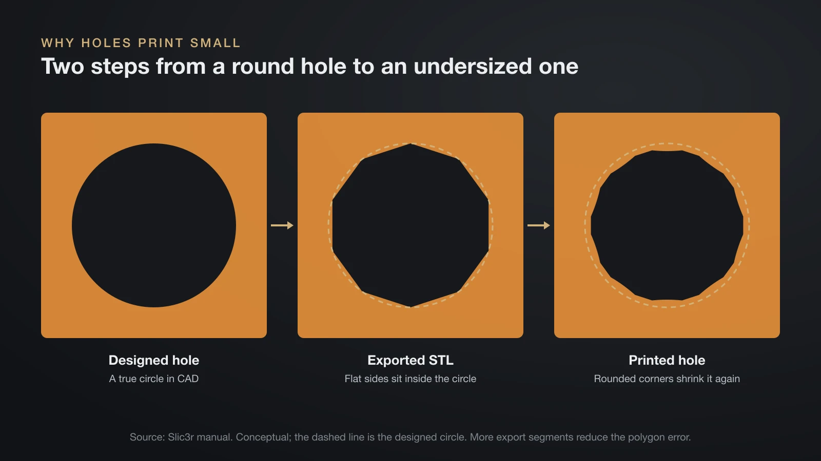
Holes usually print undersized and outer walls slightly oversized because several small errors push in the same direction. The Slic3r manual explains the first two for holes:
- Circles become polygons. An STL file stores only flat triangles, so a round hole is a polygon whose flat sides sit inside the true circle.
- Plastic rounds the corners. The extruded line cannot follow the polygon’s sharp vertices, which shrinks the hole further.
- Wall overlap shifts the outer wall. OrcaSlicer’s wiki explains that printing inner walls before the outer one can push the outer wall outward; the Slic3r manual suggests printing external perimeters first. Extra flow from over-extrusion adds to the error.
- Plastic shrinks as it cools. Bambu Lab says the effect shows most along the X and Y axes and differs between filaments.
- The first layer spreads. Elephant’s foot, a flared bottom edge, comes from the weight of the layers above, heat, a hot bed or a nozzle set too close; our guide to 3D printing first layer problems covers the fix.
Exporting circles with more segments reduces the polygon error. Check the STL export resolution in your CAD program.
Slicer settings that correct dimensions
Modern slicers can correct most dimensional errors once you have measured them, but fix flow and the first layer first. These are the settings in OrcaSlicer; Bambu Studio uses the same names for most of them:
| Setting | What it does | Where in OrcaSlicer |
|---|---|---|
| X-Y hole compensation | Grows holes (positive) or shrinks them (negative) by the set value | Process, Quality, Precision |
| X-Y contour compensation | Grows or shrinks outer contours | Process, Quality, Precision |
| Elephant foot compensation | Shrinks the first layer or layers inward | Process, Quality, Precision |
| Shrinkage (XY and Z) | Scales the part to offset the filament’s shrinkage | Filament settings, Basic information |
| Polyholes | Prints round holes as polygons sized to the true diameter | Process, Quality, Precision |
| Precise wall | Removes the overlap between outer and inner wall for truer size | Process, Quality, Precision |
| Auto circle contour-hole compensation | Applies material-based correction to round holes and shafts up to 50 mm | Bambu Studio only, Quality, Precision; tuned mainly for the H2D |
Bambu Lab’s shrinkage formula is measured size ÷ designed size × 100%: a 20 mm cube that measures 18.5 mm gives 92.5%. Bambu Lab notes that shrinkage scales outer dimensions only, so holes and contours still need the X-Y compensation settings. PrusaSlicer has its own elephant foot compensation.
3D printer tolerance test: how to run one
A 3D printer tolerance test is a small print with the same feature at several gaps, so you can read off the clearance your printer actually needs. OrcaSlicer includes one: right-click the plate, choose Add Handy Model, then Orca Tolerance Test.
- Print the test in your real material and process preset. Orca’s version has six hexagonal holes with clearances of 0.0, 0.05, 0.1, 0.2, 0.3 and 0.4 mm, plus a hexagon tester.
- Check each hole with a 6 mm Allen key or the printed tester and note the smallest one that fits the way you want.
- Measure with calipers both the holes and the tester to see whether holes, outer contours or both are off.
- Adjust X-Y hole and contour compensation, reprint and repeat until the fit is right.
- Store the result in the filament or process preset and note it next to the material, as UltiMaker suggests for designs that need accuracy.
Orca stresses that tolerances change with each printer and filament combination, even with the same profile. The other tests that should come first, especially flow, are in our guide on how to calibrate a 3D printer.
3D printed threads and screws
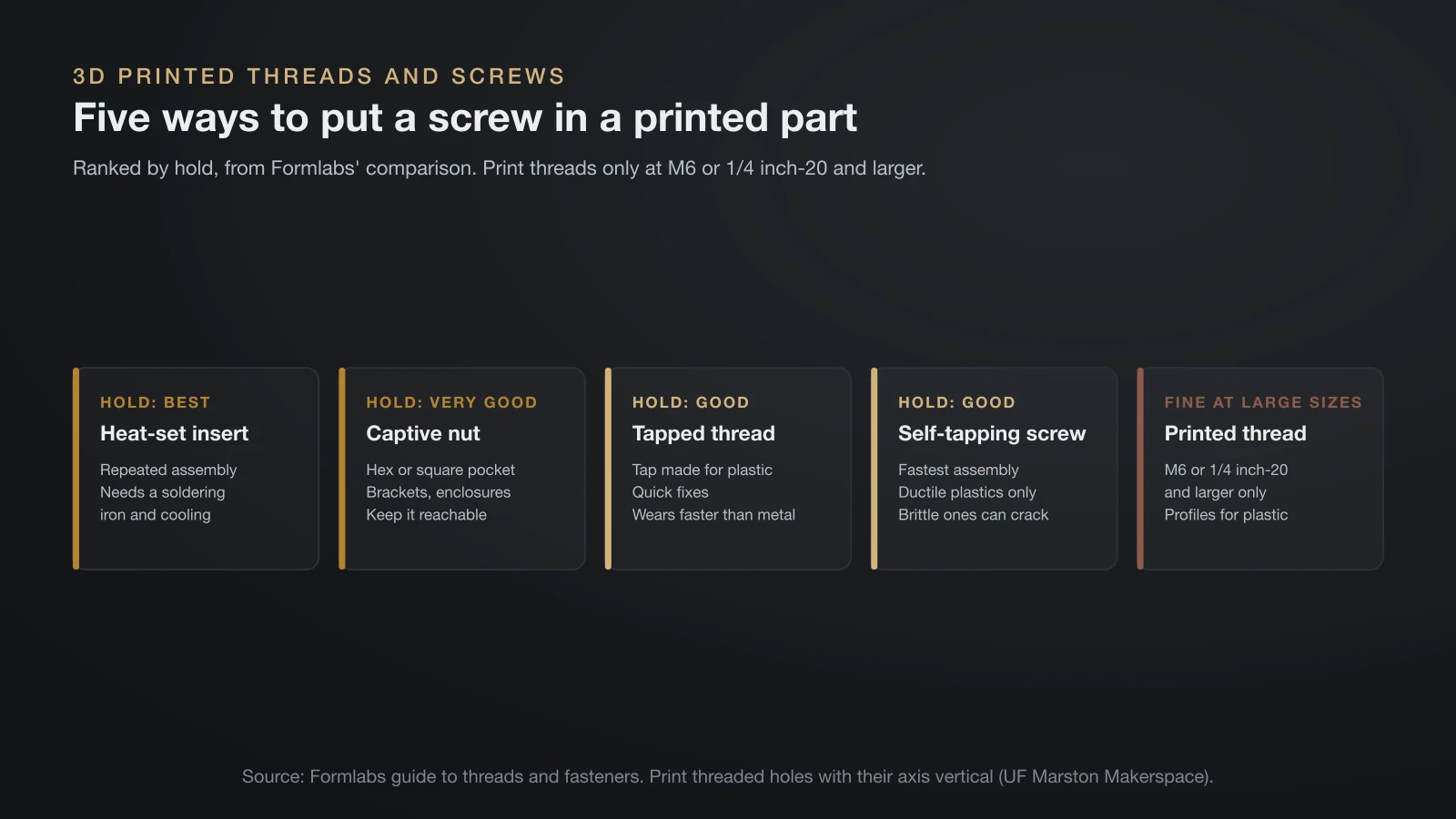
Printed threads work for large sizes, but for small screws and parts you take apart often, metal threads in a plastic part are the stronger choice. Formlabs compares the main options:
| Method | Hold | Best for | Watch out for |
|---|---|---|---|
| Heat-set insert | Best | Thermoplastic parts, repeated assembly | Needs a soldering iron and cooling time |
| Captive nut (hex or square pocket) | Very good | Simple brackets and enclosures | Pocket must stay reachable after printing |
| Tapped thread | Good | Quick fixes with a tap made for plastic | Wears faster than metal threads |
| Self-tapping screw | Good | Fastest assembly | Ductile plastics only; brittle ones can crack |
| Printed thread | Fine at large sizes | Large threads, custom profiles | M6 or 1/4 inch-20 and larger only |
Minimum size for printed threads
Formlabs recommends printing threads only at M6 (metric) or 1/4 inch-20 (imperial) and larger. Use thread profiles designed for plastic and add fillets to cut stress. For smaller sizes it suggests a custom semicircular profile on both screw and nut with a 0.1 mm offset. Resin and powder printers handle printed threads better than FDM, because they are more precise and smoother.
Print threaded holes with their axis vertical, so each layer draws a full circle; the makerspace notes that holes print best parallel to the build plate. For inserts and self-tapping screws, follow the hardware maker’s boss dimensions and add walls around the hole rather than raising infill everywhere; our guide to 3D printing infill patterns explains why walls carry more of the load. Heat-set inserts go in with a hot soldering iron, so let the plastic cool before tightening a screw.
Design tips that make fits forgiving
Good geometry makes a part tolerant of small errors, which is often easier than chasing a tighter tolerance. The University of Florida makerspace recommends:
- Lead-ins: chamfer or taper the edges of pegs, tabs and holes so parts guide themselves into place.
- Corner reliefs: add small round or triangular cut-outs (“mouse ears”) in inside corners, since FDM printers cannot make sharp inside corners.
- Teardrop holes: for holes that must run sideways, point the top of the hole so it prints without sagging.
- Compliance: use slim flexible arms, tapers or snap features that bend a little rather than demanding exact sizes.
For printed hardware such as wrench holders and drill guides, our guide to 3D printed tools shows where metal parts should take the wear.
The bottom line
Prusa puts its own FDM printers at about 0.2 mm, so on a tuned printer design gaps of about 0.15–0.20 mm for snug fits, 0.20–0.25 mm for sliding parts and 0.30–0.40 mm for loose or print-in-place ones. Fix flow and the first layer first, run a tolerance test, then dial in X-Y hole and contour compensation. Use heat-set inserts or nuts for small screws and print threads only at M6 and up.
Sources
- Prusa Research: Knowledge Base Modeling with 3D printing in mind (accuracy of at least 0.2 mm, at least 0.3 mm for movable parts, factors that change tolerances) and Elephant foot compensation
- University of Florida, Marston Makerspace: Designing for 3D Printing Tolerances on the MK4 and XL (tolerance vs clearance, Prusament PLA 1.75 ±0.02 mm, clearances by fit, print-in-place, teardrop holes, lead-ins, corner reliefs, compliance)
- Formlabs: Guide to 3D printing tolerances (SLA, SLS and FDM tolerance figures, ABS vs PLA warping), Interlocking parts (0.5 mm FDM, 0.2 mm SLA and SLS) and Screw threads and threaded inserts (insert, nut, tap and printed thread comparison, M6 minimum, 0.1 mm offset)
- Slicer documentation: OrcaSlicer Wiki Precision settings, Tolerance calibration and Filament shrinkage; Bambu Lab Wiki 3D prints shrinkage (formula, 20 mm cube example, auto circle compensation up to 50 mm); Slic3r Manual Dimension errors (polygon holes, rounded corners, more segments)
- UltiMaker: How to design for FFF 3D printing (PLA shrinks a small amount, nylon and ABS more; test print and record compensation)