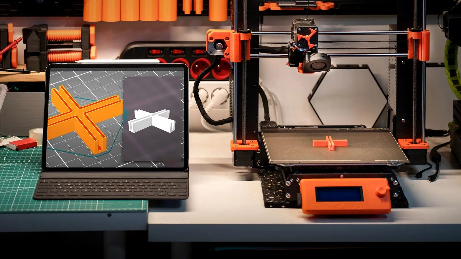
How to make 3D models for printing comes down to a short loop: choose a modeling program that suits the object, measure anything the part must fit, sketch and extrude the basic shape, apply a few FDM design rules, export an STL or 3MF file, check it in your slicer (how slicing turns STL into G-code) and run a small test print. Then adjust and repeat.
You don’t need expensive software or an engineering degree. Free browser tools handle simple parts, and free parametric CAD handles precise ones. If you only need to change a file you downloaded, our guide on how to edit STL files is the faster route, and if you are still looking for a project, start with these 3D print ideas.
The short answer
| Step | What you do | Key tip |
|---|---|---|
| 1. Pick a tool | Block-based, parametric CAD or mesh sculpting | Parts that must fit: CAD. Organic shapes: mesh |
| 2. Measure | Calipers on every surface the part touches | Measure twice, write it down |
| 3. Sketch and extrude | Draw a 2D profile, pull it into 3D | Type in dimensions, never eyeball them |
| 4. Apply design rules | Walls, overhangs, clearances, orientation | Walls in whole multiples of the line width |
| 5. Export | STL or 3MF from your modeler | Check units and export resolution |
| 6. Slice and check | Preview layers, supports and thin walls | Fix real problems in the model |
| 7. Test print | Print only the critical area first | Change one thing per round |
Three ways to make 3D models: CAD, mesh and block tools
The right program depends on what you are making. Parts that must fit something need exact dimensions, which is what CAD is built for. Figures and organic shapes are far easier in a mesh or sculpting program.
| Approach | How it works | Good for | Weak at |
|---|---|---|---|
| Block-based | Combine and subtract ready-made solid shapes | First projects, signs, simple brackets | Complex curves |
| Parametric CAD | Dimensioned sketches become features in an editable history | Functional parts, enclosures, fits | Sculpted forms |
| Code-based CAD | You write the shape as a script with variables | Customizable boxes and parts | Anything freeform |
| Mesh and sculpting | You shape a surface made of triangles | Figures, sculptures, decor | Exact holes and fits |
Example programs, one line each:
- Tinkercad: free, runs in a browser with no installation; the gentlest start.
- Autodesk Fusion: parametric CAD for Windows, Mac and iPad, well documented.
- FreeCAD: free, open-source parametric CAD for the desktop.
- Onshape: parametric CAD in the browser; the free plan covers public, non-commercial designs.
- OpenSCAD: free; you describe the model in code.
- Blender: free mesh modeling and sculpting, strong for art.
Prusa’s modeling guide notes that a parametric approach helps immensely, because you can change a dimension after a test print instead of redrawing the part. A block tool is fine for a first object; switch to parametric CAD once something has to fit.
How to make 3D models for printing, step by step
Step 1: Write down what the part must do
UltiMaker’s design guide recommends settling the requirements first: will the part carry a load, and where? Will it see heat, sunlight or chemicals, and how accurate must it be? Is it bigger than your build volume? The answers decide material, wall thickness and orientation, which is why a clip for 3D printed car parts needs different choices than a desk organizer.
Step 2: Measure the real object
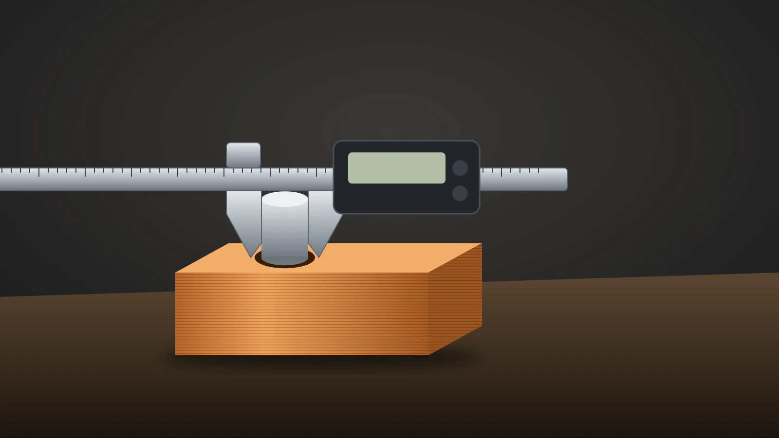
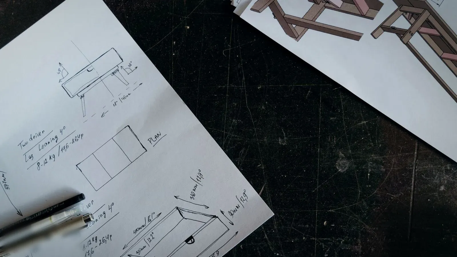
If the part fits onto, into or around something, measure it with digital calipers: hole diameters, shaft sizes, wall thicknesses and the distance between mounting points. Measure each dimension twice and write the values on a paper sketch. For curves, a straight-on photo next to a ruler helps.
Step 3: Sketch the profile in 2D
In parametric CAD, almost every part starts as a 2D sketch: lines, rectangles and circles with dimensions and constraints. Fully define it so that changing one number updates the shape, and store the values you will tweak (wall, clearance, hole size) as named parameters.
Step 4: Extrude, cut and combine
Extrude the sketch into a solid, then add or remove material with more sketches: pockets, holes, bosses and ribs. In a block tool, you place a shape, set a second one to cut and group them. In a mesh program, keep the surface closed; Prusa notes that a model with holes in its surface cannot be sliced.
Step 5: Add fits, chamfers and details
Add clearances where parts meet, chamfers on edges that touch the bed and fillets on stressed inside corners, then small details last. Save a version before merging bodies or cutting holes that must fit something, so you can step back.
Step 6: Test print and iterate
After exporting and slicing (both covered below), print only the critical area first: a slice through a hole, a short piece of a rail, one corner of an enclosure. UltiMaker suggests measuring test prints with calipers against the design. Change one dimension at a time and keep notes per material, because plastics shrink by different amounts as they cool.
Design rules for 3D printable models
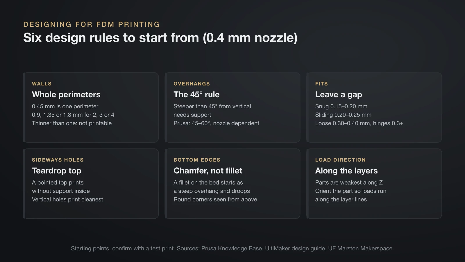
These rules assume an FDM printer with the common 0.4 mm nozzle. Treat the numbers as starting points and confirm them on your own machine.
| Feature | Rule | Numbers to start from | Source |
|---|---|---|---|
| Wall thickness | At least one nozzle width, ideally whole perimeters | 0.45 mm (1 perimeter), 0.9 mm (2), 1.35 mm (3), 1.8 mm (4) | Prusa KB |
| Overhangs | Steeper than the limit needs support | 45° from vertical; 45–60° depending on nozzle and settings | UltiMaker, Prusa KB |
| Bridges | Keep flat unsupported spans short | Shorter spans sag less | UltiMaker, Prusa KB |
| Snug or alignment fit | Gap between mating parts | 0.15–0.20 mm | UF Makerspace |
| Sliding fit | Tabs, rails, lids | 0.20–0.25 mm | UF Makerspace |
| Loose fit | Covers, print-in-place parts | 0.30–0.40 mm | UF Makerspace |
| Moving parts | Hinges | At least 0.3 mm | Prusa KB |
| Sideways holes | Pointed “teardrop” top | No support inside | UF Makerspace |
| Bottom edges | Chamfer instead of fillet | No steep overhang at the bed | UltiMaker, Prusa KB |
| Load direction | Along the layers, not across | Weakest along Z | UltiMaker |
Walls: design in whole perimeters
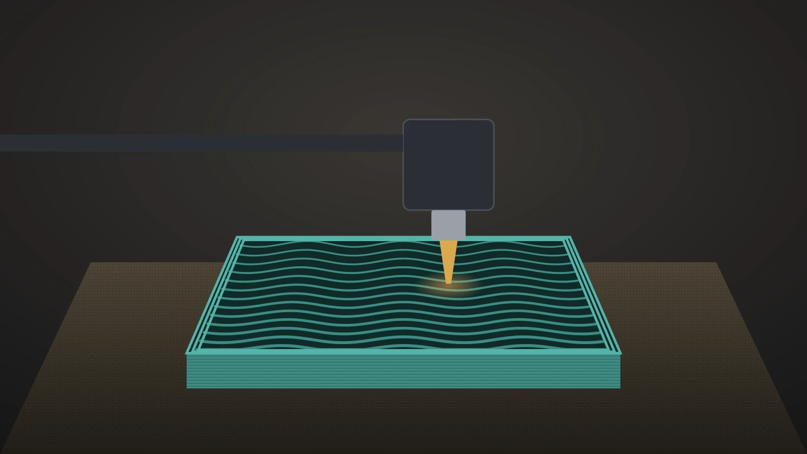
UltiMaker’s rule is that walls should be at least as thick as the nozzle diameter. PrusaSlicer prints a 0.4 mm nozzle with a 0.45 mm extrusion width, so walls work best as whole multiples: 0.9, 1.35 or 1.8 mm. Walls thinner than one perimeter are not printable, and in-between values leave gaps or odd infill.
Overhangs and the 45-degree rule
A surface that leans more than 45° away from vertical needs support underneath. Prusa puts the clean limit at 45–60° depending on nozzle and settings, up to 75° on its MK4S and CORE One printers with 360° cooling, and below 45° with a small 0.25 mm nozzle. Replace flat ceilings with chamfers, rotate the part or split it, because surfaces printed over supports come out rough.
Bridges
Short horizontal spans between two supported points print without support, as the printer drags taut lines of plastic across the gap. UltiMaker advises avoiding bridges where possible and supporting long ones: the shorter the span, the better. Keep pocket and slot ceilings narrow or give them a pointed top.
Holes, clearances and fits
Two parts with zero clearance won’t slot together. The University of Florida’s Marston Makerspace, printing on Prusa MK4 and XL machines, uses 0.15–0.20 mm for snug alignment features, 0.20–0.25 mm for sliding tabs and rails and 0.30–0.40 mm for loose covers, with print-in-place mechanisms at the larger end. Prusa suggests at least 0.3 mm for moving parts and says its printers are accurate to at least 0.2 mm.
Holes print cleanest when their axis points straight up, so each layer draws a full circle. A hole running sideways sags at the top unless you model it as a teardrop. Check the facet count of circles too, because software smooths curves on screen that print as polygons. To tune fits later, use the tolerance test in our 3D printer calibration guide.
Bottom edges: chamfer, don’t fillet
A fillet on an edge that touches the bed starts as a very steep overhang, so the bottom edge droops. UltiMaker and Prusa both recommend a chamfer instead. Rounding the corners seen from above does help, since UltiMaker notes sharp bottom corners are prone to warping.
Orientation and layer strength
Prusa compares prints to wood: they are stronger in one direction than another. UltiMaker adds that FDM parts are usually weakest along the Z axis, so plan orientation while you design. Lay clips, hooks and brackets so the force runs along the layers.
Split big or awkward parts
Splitting lets each piece print in its best orientation with fewer supports. PrusaSlicer’s cut tool can split a finished model and add plug, dowel or snap connectors, but designing the split in CAD with alignment pegs is cleaner. Glue smooth, clean faces, and expect seams to show more on small models.
How to make 3D printer files: STL, 3MF or STEP?
Making 3D printer files is the export step, and the format decides what information survives it.
| Format | What it stores | Use it for |
|---|---|---|
| STL | Surface triangles only; no units, color or settings | The universal hand-off to any slicer |
| 3MF | Triangles plus units, multiple objects, color, texture and slicer settings | Your default when your tools support it |
| STEP | CAD solid with exact curves | An editable master to share with CAD users |
STL measurements are unitless, so the program that opens the file has to assume a scale. A 3MF bundles several models, settings, a thumbnail, color and texture in one archive, and Prusa notes it is significantly smaller than an STL. PrusaSlicer also opens STEP files, triangulating them on import.
Check two export settings. Units: Onshape lets you choose the units written into an STL, and a part exported in inches arrives far too small in a millimeter slicer. Resolution: presets from Coarse to Fine, or custom chordal tolerance and angular deviation, decide whether circles print round or as polygons. Keep the native CAD file or a STEP as your master.
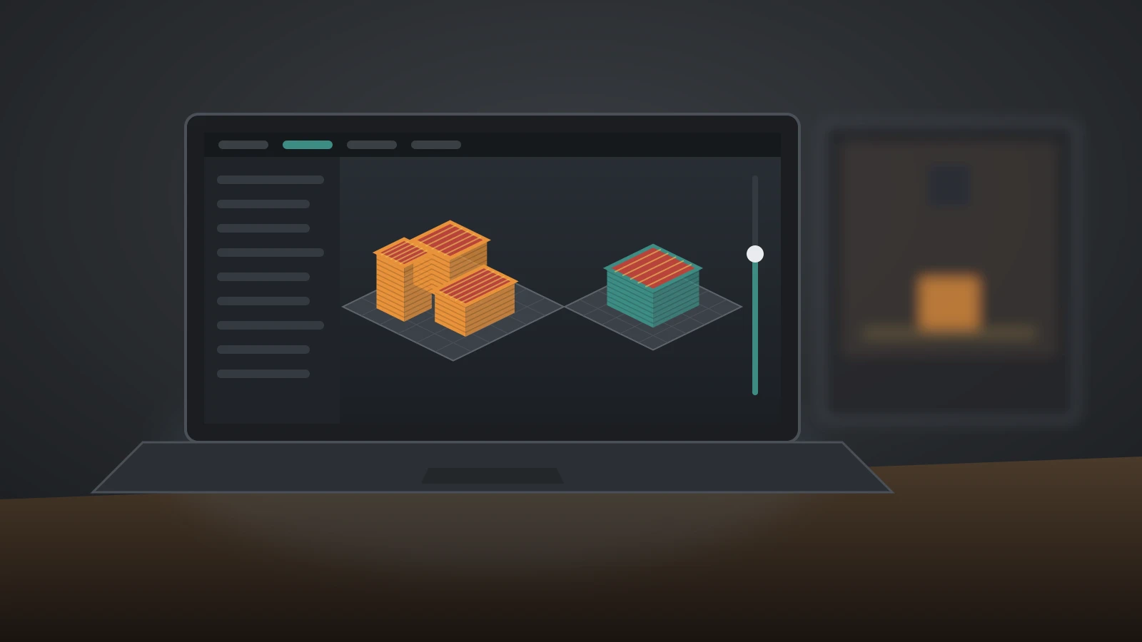
Check your model in the slicer before printing
The slicer is your last free chance to catch a mistake:
- Size: a tiny or giant model usually means a units mismatch.
- Errors: slicers repair small mesh errors, but warnings about open edges mean the model needs fixing.
- Orientation: put a large flat face on the bed, with loads running along the layers.
- Layer preview: walls that vanish are thinner than one line; islands in mid-air need support.
- Supports: unexpected supports point to overhangs worth redesigning.
Good first projects to practice on
- A cable clip or hook: sketching, extruding and orientation for strength.
- A box with a sliding lid: print the lid with two or three gap sizes and keep the best fit.
- A blocky figure: flat faces print cleanly, which makes Minecraft 3D prints good practice.
- A replacement knob: measuring a real shaft and matching it.
- A mold box: the first step if you want to cast silicone parts from a printed mold.
The bottom line
To make 3D models for printing, choose a tool that fits the job, measure first, sketch with real dimensions and design around the printer’s limits: whole-perimeter walls, the 45-degree rule, short bridges and clearances of roughly 0.15–0.40 mm depending on the fit. Export a 3MF or STL with the right units and resolution, check it in the slicer and test the critical area before printing the whole part. Keep the editable CAD file, because the second version is almost always better.
Sources
- Prusa Knowledge Base: Modeling with 3D printing in mind, Creating your own 3D models, Cut tool, Supported file formats and Saving projects as 3MF (nozzle, extrusion width and wall values, overhang angles, 0.2 mm accuracy, 0.3 mm hinge clearance, chamfers, software, file formats)
- UltiMaker: How to design for FFF 3D printing (45-degree rule, minimum wall, bridges, bottom-layer chamfers, weakness along Z, test prints)
- University of Florida, Marston Makerspace: Designing for 3D Printing Tolerances on the MK4 and XL (clearances by fit type, teardrop holes)
- University of Maryland: Slicing and 3D Printing File Types Overview (unitless STL, 3MF contents, G-code)
- Onshape: Exporting files and Free plan (STL resolution and units; free plan terms)